Products
We provide one-stop product solutions.
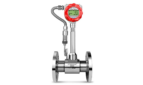
Vortex flow meter
The LUGB series vortex flowmeter is a new type of flowmeter introduced by our company, featuring a reasonable design, powerful functions, and leading-edge linear correction capabilities. It utilizes a sophisticated, low-power 45×30 full-dot matrix LCD display for clear and intuitive operation. RS485 or HART communication options meet various user needs, and multiple compensation algorithms can satisfy almost all flow compensation calculations.
Product Advantages
Product Introduction
Working principle
The basic principle of the intelligent vortex flowmeter is the Kármán vortex street principle, which states that “the vortex shedding frequency is proportional to the flow velocity.” The diameter of the flowmeter’s main body is essentially the same as the instrument’s nominal diameter. As shown in Figure 1, a roughly isosceles triangular prism is inserted into the flow body. The axis of the prism is perpendicular to the direction of the measured medium’s flow, with its base facing the fluid. When the measured medium flows past the prism, vortices are alternately generated on both sides of the prism. These vortices are continuously generated and shed, forming two staggered rows of vortices downstream of the prism, known as the “vortex street.” Theoretical analysis and experiments have proven that the vortex shedding frequency is directly proportional to the fluid velocity on the sides of the prism.
F = Sr V/d
Where: f — frequency of vortex shedding from the cylinder (Hz)
V — flow velocity at the cylinder side (m/s)
d — width of the cylinder’s leading edge (m);
Sr — Strouhal number, a constant that depends on the cross-sectional shape of the cylinder and is essentially independent of the fluid properties and flow velocity; Sr: 0.17–0.18.
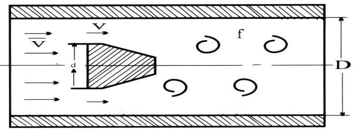
In the above equation, d and D are known structural dimensions, and Sr is a constant. Therefore, by measuring the vortex shedding frequency f,
the average flow velocity inside the pipe can be determined, and thus the flow rate Q can be calculated: Q = 3600S·V (m³/h).
Where: S – the cross-sectional area of the flow meter body (m²)
V – the average flow velocity in the flow meter body (m/s)
The intelligent vortex flowmeter is designed such that the width of the bluff body (d) has a fixed ratio to the diameter of the flow pipe (D). Therefore, the average flow velocity (V) through the pipe has a fixed ratio to the flow velocity (V’) at the side of the bluff body:
Features
▲ Non-blocking design: The entire sensor and wetted parts are made of stainless steel, with a simple structure and no moving parts, minimizing the risk of failure due to holes, gaps, and gaskets.
▲ Mechanical vibration resistance: The company has optimized the circuit design to effectively filter out vibration frequencies caused by mechanical vibrations.
▲ Simplified troubleshooting: The sensor is isolated from the process, ensuring easy installation, constant instrument coefficients, high data repeatability, good compatibility between the converter and the sensor, and convenient and quick maintenance.
▲ System stability: The detection sensor does not directly contact the measured medium, and features water hammer and lightning protection designs. The housing is corrosion-resistant and dirt-resistant; long-term system testing has proven its stable performance, long service life, high temperature resistance, and high reliability.
▲ Analog and digital signal processing: The converter adopts advanced circuit design, allowing for both manual analog settings and adaptive digital processing. It features no zero-point drift, high accuracy, a wide measurement range, a typical range ratio of 10:1, and a maximum of 15:1.
Main technical parameters
| Nominal diameter | 15, 20, 25, 32, 40, 50, 65, 80, 100, 125, 150, 200, 250, 300… |
| Pressure Level | PN16 (larger than PN16, order by agreement) |
| Medium and temperature | Medium: liquid, gas, steam, thermal oil; temperature: -20~250℃; -20~350℃ |
| Body material | SS304; SS316L agreement ordering |
| Allow vibration acceleration | 0.2g |
| Accuracy | Level 1.0; Level 1.5; Level 2.5 |
| Turn down | 1:6; 1:10; 1:15 |
| Supply voltage | 3.6V battery; DC24V |
| Output signal | Pulse, 4~20mA, RS485, Hart protocol |
| Explosion-proof signs | ExdII CT6 Gb |
| Protection level | IP65;IP68 protocol ordering |
| Environmental conditions | -20~55℃; relative humidity: 5~95%; atmospheric pressure: 86~106Kpa |
| Show | No display; LCD display |
| Electrical Interface | M20X1.5;NPT1/2 |
Instrument Structure and Installation Dimensions
Ordinary clamping size
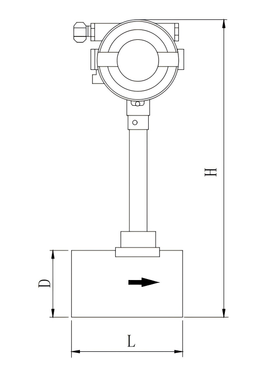
| Ordinary body | |||
| Nominal diameter | Long L | Outer diameter D | Total high H |
| 15 | 80 | 6 3 | 364 |
| 20 | 80 | 6 3 | 364 |
| 25 | 80 | 6 3 | 364 |
| 32 | 80 | 6 3 | 364 |
| 40 | 80 | 78 | 384 |
| 50 | 80 | 78 | 384 |
| 65 | 80 | 100 | 404 |
| 80 | 100 | 113 | 427 |
| 100 | 100 | 132 | 436 |
| 125 | 100 | 158 | 479 |
| 150 | 110 | 180 | 506 |
| 200 | 140 | 240 | 589 |
| 250 | 160 | 298 | 615 |
| 300 | 180 | 350 | 666 |
Ordinary flange connection dimensions
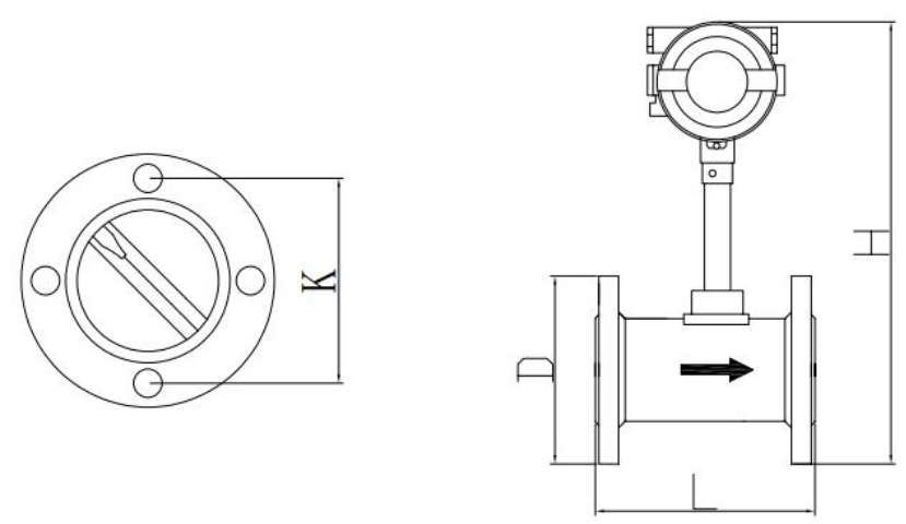
| Ordinary flange connection body | |||||
| Nominal diameter | L | D | H | K | n*φ |
| 15 | 200 | 95 | 381 | 65 | 4*14 |
| 20 | 200 | 105 | 386 | 75 | 4*14 |
| 25 | 200 | 115 | 391 | 85 | 4*14 |
| 32 | 200 | 140 | 404 | 100 | 4*18 |
| 40 | 200 | 150 | 419 | 110 | 4*18 |
| 50 | 200 | 165 | 426 | 125 | 4*18 |
| 65 | 200 | 185 | 446 | 145 | 4*18 |
| 80 | 200 | 200 | 465 | 160 | 8*18 |
| 100 | 200 | 220 | 471 | 180 | 8*18 |
| 125 | 250 | 250 | 499 | 210 | 8*18 |
| 150 | 300 | 285 | 530 | 240 | 8*22 |
| 200 | 300 | 340 | 583 | 295 | 12*22 |
| 250 | 300 | 405 | 643 | 350 | 12*22 |
| 300 | 300 | 460 | 695 | 400 | 12*22 |
Flow rate range table by pipe diameter
| Flow rate range(m³/h) | ||
| Nominal diameterDN(mm) | liquid | gas |
| 15 | 0.6~6 | 3~12 |
| 20 | 1~10 | 5~30 |
| 25 | 1.6~16 | 8~70 |
| 32 | 2.2~20 | 15~150 |
| 40 | 2.5~25 | 20~200 |
| 50 | 3.5~35 | 35~350 |
| 65 | 6.5~68 | 50~500 |
| 80 | 10~100 | 70~700 |
| 100 | 15~150 | 110~1500 |
| 125 | 27~275 | 150~1500 |
| 150 | 40~400 | 250~2200 |
| 200 | 80~800 | 600~4000 |
| 250 | 120~1200 | 960~5500 |
| 300 | 180~1800 | 1500~11500 |
FAQ
We provide you with the advantages of a reliable manufacturer.
Are you the source factory?
Yes. We are a professional manufacturer of flow meters and Industrial instrument, production, sales, and service. With excellent processing equipment and advanced technology, we have received multiple honors and customer praise.
What can you buy from us?
We have products like oval gear flow meter, turbine flow meter, electromagnetic flow meter, vortex flow meter, mass flow meter, ultrasonic flow meter, radar level meter, precession vortex flow meter, etc.
How long is the warranty period?
Standard one year warranty, and lifetime technical support is provided for all our client.
How can we guarantee quality?
All the flow meter and sensor have passed the national quality inspection and obtained ISO certification for quality management system certification, CE certificate, high-tech enterprise certificate, calibration certificate and all the products will be verified as qualified before shipment.
After I paid,how long will the delivery take?
Standard: 1-2 working days shipment
Custom models or in bulk: negotiate the specific time
Can you provide installation videos or manuals for us?
Sure thing, we’ll provide English manual and tutorials for you. For all our client, And our technical engineers are always at your service!